WCST
In this section we describe the load case "WCST" available in Oliasoft WellDesign™.
The well containment screening tool WCST is a collapse load case, where the unknown is the internal pressure profile of the tubing. //: # (end - introduction)
NOTE!
Note: In this documentation we denote any tubular as tubing. All calculations however encompass any tubular, such as tubings, casings, liners, tie-backs etc.
Summary
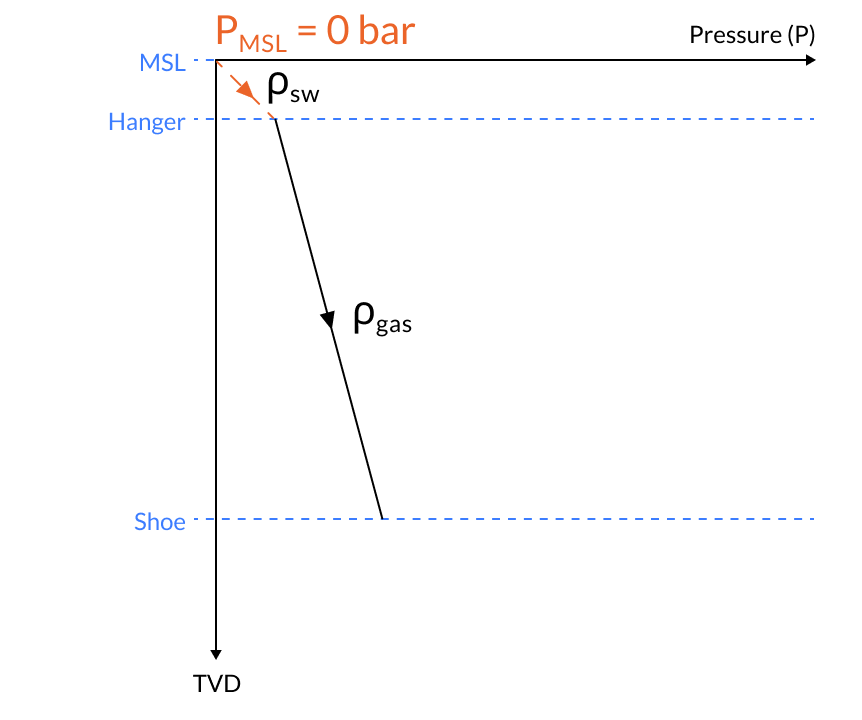
The well containment screening tool is a set of criteria for collapse load recommended by the Bureau of Safety and Environmental Enforcement to check if the well can be capped in case of a worst case discharge scenario. The pressure profile is given by the hydrostatic sea water gradient from mean sea level to the hanger and hydrostatic gas gradient from the hanger to the casing shoe. //: # (end - summary)
Illustrating Pressure Profile Graph
Printable Version
Oliasoft Technical Documentation - WCST
Inputs
The following inputs define the WCST load case:
- The true vertical depth (TVD) along the wellbore as a function of measured depth. Alternatively, the wellbore described by a set of survey stations, with complete information about measured depth and inclination.
- The true vertical depth / TVD of
- The hanger of the tubing, TVD.
- The shoe of the tubing, TVD.
- The mean sea level, TVD.
- The mudline, TVD.
- The temperature profile of the wellbore, T.
- The density of seawater, .
- The gas/oil gradient, , or gas specific gravity, .
- The gravitational constant, . //: # (end - inputs)
Calculation
If the hanger of the tubing is above mean sea level (MSL), then from the hanger to MSL
= 0,
and from MSL to the mudline
The internal pressure from mudline to shoe is the affine profile in TVD based on and .
External profile
The external pressure profile for this load case is given by the hydrostatic pressure based on the fracture gradient at the previous shoe and mud at shoe, from hanger to top of cement, and pore pressure in cement. //: # (end - calculation)
References
[1] Curtis H. Whitson and Michael R. Brul. Phase behavior, volume 20 of Henry L. Doherty series. SPE Monograph series, 2000.