Displacement To Gas
In this section we describe the load case "Displacement to gas" available Oliasoft WellDesign™.
Displacement to gas is a burst load case, where the unknown is the internal pressure profile of the tubing.
NOTE!
In this documentation we denote any tubular as casing or tubing. All calculations however encompass any tubular, such as tubings, casings, liners, tie-backs etc. //: # (end - note)
Summary
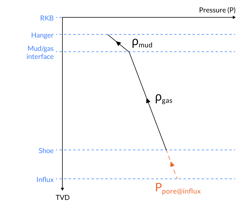
The scenario is a gas kick during drilling of the next open hole section somewhere below the casing shoe. The internal pressure is determined from the pore pressure at the influx depth, and extrapolation of a gas gradient from the influx depth to the mud/gas interface, and then a mud gradient from the mud/gas interface to the hanger. It is also possible to specify “Limit to frac at shoe”. If this option is selected and the pressure at the casing shoe is higher than fracture pressure, the maximum pressure at the casing shoe is set to equal the fracture pressure.
Illustrating Pressure Profile Graph
Printable Version
Oliasoft Technical Documentation - Displacement To Gas
Inputs
- The true vertical depth (TVD) along the wellbore as a function of measured depth. Alternatively, the wellbore described by a set of survey stations, with complete information about measured depth and inclination.
- The true vertical depth/TVD of
- The hanger of the tubing, TVD
- The shoe of the tubing, TVD
- The influx depth of the gas, TVD
- The gas - mud interface, if the gas doesn't displace all the mud, TVD
- The pore- and fracture- pressure profile from hanger to influx depth.
- The mud weight/density
- The gas - oil gradient, i.e. the density of gas, .
- Whether or not to limit the pressure at shoe by the fracture pressure there. If this is enabled, it is also possible to give a fracture margin or error, which is aded to the fracture pressure. //: # (end - inputs)
Scenario Illustration
.gif)
Calculation
The hydrostatic internal pressure profile of the tubing is calculated from the gas - mud interface down to the shoe and up to the hanger. The algorithm goes as follows
-
Calculate the pore pressure at influx depth,
-
Calculate the fracture pressure at shoe,
-
Calculate the hydrostatic pressure at the shoe from the pore pressure at influx depth and the gas-oil gradient, i.e.
where is the gravitational constant.
-
The pressure at the shoe depends on whether 'Limit to frac at shoe' is enabled, and whether the hydrostatic pressure at the shoe, is greater than or equal to the fracture pressure at the shoe, . Precisely, the pressure at the shoe is
-
Calculate the internal pressure profile of the tubing, as the hydrostatic pressure from shoe to hanger.