Gas Over Mud Ratio
In this section we describe the load case "Gas Over Mud Ratio" available in Oliasoft WellDesign™.
Gas over mud is a burst load case, where the unknown is the internal pressure profile of the casing / tubing.
NOTE!
In this documentation we denote any tubular as casing or tubing. All calculations however encompass any tubular, such as tubings, casings, liners, tie-backs etc. //: # (end - note)
Summary
The scenario is a gas kick somewhere below the shoe of the tubing, i.e. in the open hole of the next section, which moves upwards to the hanger and displace the mud. This load case can be viewed as the equilibrium of the load case Displacement to gas, although some of the inputs are different. This load case comes with two additional choices.
It is possible to enable Limit to frac at shoe, which effectively limits the maximum pressure at the shoe to the fracture pressure there, and also to enable MASP / MAWP (Maximum Anticipated Surface/Wellhead Pressure), which then gives the internal pressure as the interpolated pressure between MASP / MAWP and fracture pressure at shoe. If both are enabled, then MASP / MAWP takes precedence.
Illustrating Pressure Profile Graph
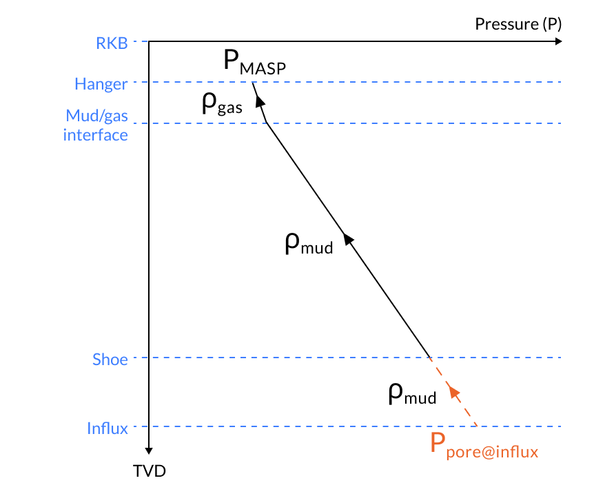
Graph 1: Illustrates a case where the Limit Frac@shoe and MASP/MAWP to Frac@Shoe is turned off.
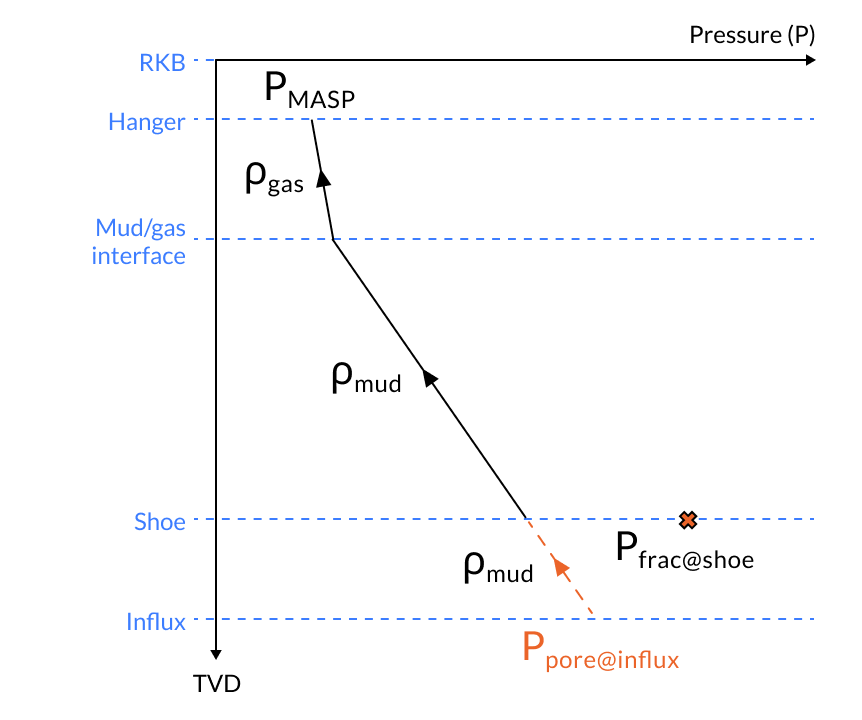
Graph 2: Illustrates a case where the Limit Frac@shoe is turned on and MASP/MAWP to Frac@Shoe is turned off. The pressure at the casing shoe is below the fracture pressure, thus the pressure is not affected.
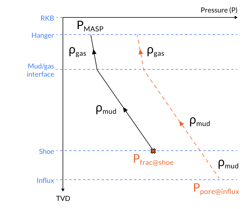
Graph 3: Illustrates a case where the Limit Frac@shoe is turned on and MASP/MAWP to Frac@Shoe is turned off. The pressure at the casing shoe is above the fracture pressure, thus the pressure at the casing shoe is limited to the fracture pressure.
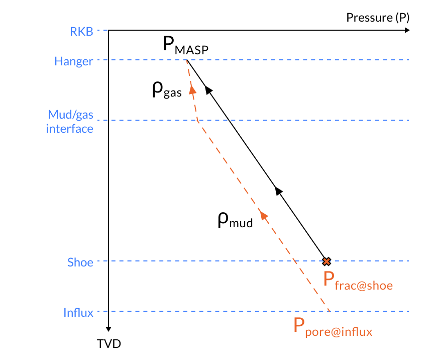
Graph 4: Illustrates a case where the MASP/MAWP to Frac@Shoe is turned on. The pressure at the casing shoe is then set to the fracute pressure, then pressure at hanger is set to MASP and the pressure graph is interpolated between the two data points.
Printable Version
Oliasoft Technical Documentation - Gas Over Mud Ratio
Inputs
The following inputs define the gas over mud load case
- The true vertical depth (TVD) along the wellbore as a function of measured depth. Alternatively, the wellbore described by a set of survey stations, with complete information about measured depth, inclination, and azimuth.
- The true vertical depth / TVD of
- The hanger of the tubing, TVD
- The shoe of the tubing, TVD
- The influx depth of the gas, TVD
- The pore- and fracture- pressure profile from hanger to influx depth.
- The gas over mud ratio,
- The mud weight/density,
- The gas density,
- Whether or not to limit the pressure at shoe by the fracture pressure there. If this is enabled, it is also possible to give a fracture margin of error, which is added to the fracture pressure.
- Whether or not to enable MASP/MAWP.
Scenario Illustration
Calculation
The internal pressure profile of the tubing is calculated as the hydrostatic pressure from hanger to shoe. The algorithm goes as follows
-
Calculate the true vertical depth of the gas-mud interface, . This interface is then either above the tubing shoe, or below it.
-
Calculate the pore pressure at influx depth, , and the fracture pressure at the shoe,
-
Calculate the hydrostatic pressure at the shoe, from and up
where is the gravitational constant.
-
Calculate the pressure at the shoe as
-
Calculate the internal pressure of the tubing as the hydrostatic pressure from hanger to shoe.
-
If MASP/MAWP is enabled, this take precedence, and then the internal pressure profile of the tubing is given by the interpolated pressure of the MASP/MAWP, i.e.
and the fracture pressure at the shoe, . //: # (end - calculation)